UNDERGROUND RADIO
by Le Magicien
During World War II there were situations were conventional radio was useless, either because enemy jamming or just for hidding purpouses; thus, radio operators forced off the air, tried a different aproach... underground radio. Although it's obviously a less efficient system, it works perfectly well if we find a good conductive sheet beneath.
THEORY
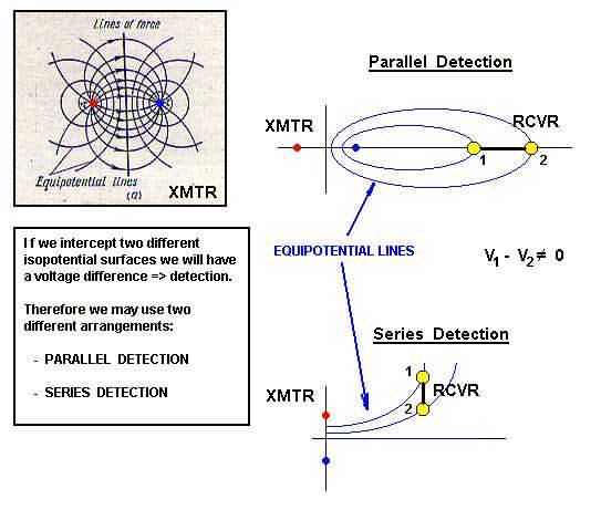
Imagine a DC (or AC) generator, one end connected to the ground and the other terminal to the antenna. If we bury the antenna some meters from the ground terminal, we will have a force field/ current field analog as the one show at left.
The two points A and B represent the transmitter terminal electrodes buried in the ground; the voltage difference applied between them (the signal to be transmitted that is fed directly into the earth) will produce a current flow (shown in red) and equipotential surfaces (shown in blue).
Because the earth is a mixture of water and minerals, thus a highly conductive medium (in fact it behaves as a chemical electrolyte), but an unhomogeneous one, the signal will be distributed unevenly, with maximum in areas of lowest resistance.,
From this we conclude that is very important to bury the "antenna" as deep as posible, in order to reach the water table.
How to detect the signal?
Well, if we intercept two different equipotential lines, we'll have a voltage difference that we may detect, filter and amplify.
The interception of two different equipotential lines may lead us to two basic receiving modes: parallel and series detection, as shown on the figure on the left.
The yellow dots represent the ground and receiving antenna terminals of the receiver.
CONSTRUCTION TIPS
TRANSMITTER
Usually, the XMTR is an audio amplifier of 15 watts or more connected to the grounded terminals rods A and B. As always, maximum performance will be obtained when the soil impedance matches the amplifier output impedance.
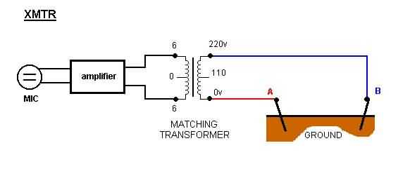
Common audio amplifiers have an output impedance between 4 to 8 ohms, but soil impedance may range from few to several megohms, therefore it's necessary to use a matching transformer.
We may use a 6 + 6 (or 9 + 9) center tap xfmr (6+6/110-220v), with a secondary (the low voltage side) of 500mA).
The secondary (low tension and low resistance) side is connected to the amplifier output, and the 110/220v side to the XMTR terminal rods A and B buried in the ground.
RECEIVER
For the receiver section we may use the same configuration with a matching transformer, coupled with a diode detector and high impedance headphone connected directly to terminals MT1 and MT2.
A better approach consist in using a walkman headphone (low impedance) with an impedance coupler/amplifier unit built around 2 transistors.
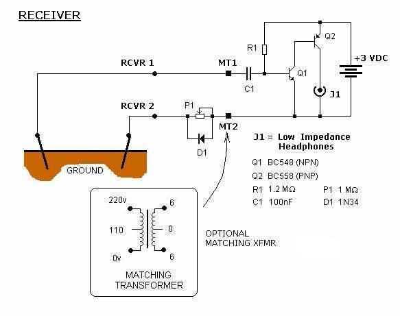
Another approach may be tested, but requires using a high impedance headphone, usually of more than 20 kohms. As before, coupling P1 to the diode D1 will select mainly underground radio signals, mostly VLF ones; decoupling will select audio ones.
Remember that the "underground antenna" must be separateed by at least 5 meters from the grounding electrode to prevent the incoming signal to be short-circuited by the low resistance between them.
