A simple loop, including preamp, for longwave. As most of the local QRM is mainly caused by the electric field a loop antenna can cancel out much of the noise in a high-noise enviroment.
In an environement with a lot of 'vertical objects' (trees etc.) close to the antenna inductive toploading can significantly increase the performance of a short vertical antenna.
Tuning a LF antenna can be tricky. An antenna that's much shorter than a quarter wavelength will have a high Q and consequently a narrow bandwidth. A loading coil with a series of taps can be used, but a constantly adjustable inductor like a variometer will make tuning a lot easier.
Loop antennas offer many advantages for LowFER reception. They're compact, don't need to be high and in the clear, and their directional characteristics can be used to null out local noise or strong interfering signals. Unfortunately a loop doesn't offer a good impedance match to a coaxial transmission line or to the input of most modern receivers.
Also, unless the loop is balanced and shielded, the so-called antenna effect makes the loop act like a combination of a loop and a short vertical whip. The directional pattern becomes asymmetrical and the nulls off the side may be only a few dB down from the peak of the radiation pattern. An unbalanced, unshielded loop can also pick up conducted interference from the feed line.
You might find a quiet location in the "back 40", put your loop out there, and then re-introduce the noise from the house when you connect the coax. Shielding adds distributed capacitance to the loop and reduces the Q, which in turn reduces the loop's sensitivity. This article gives some ideas on how to use a simple unbalanced loop with a home-brew transformer to achieve most of the benefits of a shielded, balanced loop.
The octoloop is a length of 25 pair telephone wire inside an octagonal loop shield of 3/4 hard copper pipe. Mine is about 7 ft dia and wired for 50 turns, and gimballed for noise rejection. The pipe shield is a very effective electrostatic shield at MF, and also reduces VLF/ULF microphonics, which for obvious reasons plague most loops. The self resonant freq has not yet been measured, but is probably near 12kHz.
The back garden at GW4ALG is only 15 m long by 11 m wide, so the real challenge presented by operating on 136 kHz is trying to make electrically-short antennas (i.e. antennas that will fit into the garden) actually radiate RF energy.
My loop started life as a full-size G5RV antenna in inverted-vee format (basically, a centre-fed inverted-vee dipole, overall length of 34 m, fed with 13 m of feeder). For 136 kHz, I joined the far ends of the dipole together with some thick multi-strand cable to form a sort of top-fed delta loop having an overall perimeter of about 65 m.
This tuner was devised to provide a method of fine-tuning the experimental vertical antenna. This remotely-controlled tuner has enabled me to change frequency much more quickly than previously, when I only had the larger variometer with which to make such adjustments. (Not easy with an upstairs shack; and the loading coil/variometer positioned in the garden!)
LF antenna matching can be done with a relatively small ferrite pot-core instead of big coupled air coils. The air-gap variometer designed by DK5PT is compact and can be used up to 300W output power.
Getting on the air with a LowFER station is more complicated than getting on the ham bands since commercial equipment isn't available and construction is involved. The "RB" LowFER antenna is 31 feet tall with a 24 foot diameter top hat. At 186 kHz, the antenna primarily looks capacitive with a small resistive component consisting of the radiation resistance of the antenna in series with the loading coil resistance and the ground resistance. These three resistances are the factors under control of the experimenter and determine how well the antenna works. The radiation resistance of any Part 15 antenna is a small fraction of an ohm, since the 15 meter length limitation means that the antenna will be less than 1 % of the wavelength, as opposed to 25 % which is the generally accepted rule for AM broadcasting and 160 M ham operation.
About a year ago I made a receiving loop for 136kHz using computer ribbon cable housed in plastic waste pipe. It wasn't very successful. It would appear that the low Q caused by the construction of the ribbon cable was the problem. I have since made the G3LNP loop although I had difficulties with the amplifier. I finished up using a low impedance pick-up loop without the amplifier - this worked reasonably well but it did lack sensitivity.
I decided to redesign the plastic waste pipe special because if its inherent weather resistant structure This time I made it twice the size and used Litz wire from the Crawley club source. This antenna turned out to be very good and outperformed all other loops built previously. Furthermore, this design does not need an amplifier. A description of its construction follows.
How would you like to put together an antenna for the broadcast and longwave bands that's as good as those expensive loops for under $10 ?
The author has been interested in long distance m.f. reception for many years from both international and local radio stations. Added to this has been the fascination of using the "null" effect of balanced loop antennas to aid reception where co-channel interference and/or local noise is a problem However, the author has insufficient space in the shack to seriously experiment or use loops of any size. This article describes a solution to this problem by remotely tuning a relatively large m.f. loop which is mounted in the loft space some distance from the operating position.
The loop design for this application is not critical and can be built in size and style to individual preference. The article in reference I discusses the background, design, construction and use of m.f. loop antennas and is well worth reading.
Remark : although this antenna is intended for MF it should be easy to adapt it for LF.
Measuring field strengths is essential to be able to determine your ERP. A simple field strength meter for 136kHz was developed by PA0SE. Description includes the calibration procedure.
A standing wave ratio meter for LF. Good matching is essentail, also on LF. While most commercial VSWR meter (intended for HF) will be very insensitive on LF, this one is designed for 136kHz
Measuring HF currents without breaking the wire. With a clamp-on current probe you can measure the RF-current in a wire without beaking the wire (to insert a more traditional amp-meter). This design will work from 100kHz up to 10MHz.
A simple tool to measure the resistance of your LF antenna
With a few components you can built a reference signal source that can be used to calibrate your receiver. As most receivers are intended to be used on HF the S-meter is ofter very incorrect on 136kHz. Using a reference source you can calibrate your S-meter and give correct reports.
In February and March 2000 some measurements were made with a home-brewed field strength meter. The meter setup has been somewhat reconfigured during the test period. First I used an untuned loop as "sensing element". Later this was replaced with a tunable ferrite rod probe with a 11 dB FET preamp. The ferrite probe was calibrated and linearity checked between 0,5 mV/m and 10 mV/m with a pair of Helmholtz coils.
For those of us who like to play with antennas on the ham bands, one of the handiest tools to have around the shack is an antenna analyzer. These gadgets combine a signal generator and standing-wave ratio (SWR) sensor in a small battery-powered unit. I wanted an analyzer that would operate in the 100 to 300 kHz range and would measure antenna system resonance, system losses and antenna capacitance, as well as the inductance and Q of loading coils and receiving loops.
Learn how to adapt the popular MFJ-259 antenna analyzer to tune down to 100kHz.
I found this circuit to perform very well in my 136 kHz transverter and have subsequently used it in my Loop ATU and my 400 W Power Amplifier with great success. It easily copes with 400 W of RF, and probably a lot more besides. Dave, G3YMC has also used this design in his 136 kHz transverter.
 (29 August 2001)
This simple instrument can be used to use impedances at LF. You will need a signal source with at least 6Vpp, almost any LF generator can be used. The author uses this bridge to match the loadingcoil to 50 Ohm before transmitting.
Receiver pre-amplifiers for LF. If you are using a deaf receiver and/or a small antenna for reception on LF a preamp may improve your receiving system.
A balanced loop preamp can be found here.
Converts longwave to the 10 meter amateur. If your receiver does not cover 136kHz a converter can be used to upconvert the LF-segment to 28MHz.
A LF up-convertor using CMOS switches (74HC4053) as mixer.
Most modern tranceivers cover LF but the performance is not always very good. All you can hear are strange whistles and burbles which aren't really there! You need this little circuit. It has a gain of about 10dB and a nice sharp band-pass response about 3kHz wide, enough to cover the 136 band.
If you want to use a small multi-turn loop on LF, you will find that the sensitivity is not good enough to receive the weaker signals. A good preamp for a loop needs to have a high input impedance and good signal handling characteristics (to prevent cross-modulation).
Here is a preselector circuit designed by Wolf DL4YHF as part of his transverter. It uses two pot-core filters with FETs and feedback. By adjusting the controls, the bandwith can be set to less than 200Hz. This is the preamp which Wolf uses at the club station DF0WD.
Many simple designs for low frequency converters have been published over the years. However, most of these designs used basic single-ended mixers with only fair performance in terms of sensitivity and dynamic range, and this has created the perception that a converter is a second-rate method of LF reception. That is unfortunate, because a well-designed converter working into a modern receiver will deliver performance on par with virtually any radio designed for LF.
Perhaps calling this a universal preamp is stretching things a little, but it works on the LF and MF bands with loop, whip or random-length wire antennas. Regeneration can be used with any type of antenna, although the circuit provides very high gain even without it. Because of its versatility, this preamp is ideal for experimenting with various types of receiving antennas. This article also shows how the preamp can be powered and tuned remotely, with only a single coax line between the remote antenna site and the receiver.
A RX filter with an insertion loss is 5.2dB at 136.5kHz, a 6dB bandwidth of 2.2kHz and a 60dB bandwidth of 26.3kHz.
Here is a little circuit I put together one evening so I could use a high-impedance E-field probe antenna with my commercial general coverage receiver. I wanted something small and simple which I could use mobile, and which would run on its own batteries so that noise from the car DC supply would not be introduced.
(6 July 2001)After replacing a Kenwood TS-850 by its 'big brother' the Kenwood TS-950 Alberto was rather dissapointed by the sensitivity of the TS-950 on LF. In this article he shows how the source of the insensitivity was located and a cure was found
(6 August 2001)Historic VLF station "SAQ" was put back on the air on 17.2kHz for a day of special transmissions on 1st July 2001. This inspired Jim Moritz, M0BMU, to construct an appropriate receiver for the event :
"I was able to successfully receive SAQ with a homebrew electro-mechanical receiver. As far as I know, the Alexanderson alternator at SAQ is currently the only operating radio station with an electro-mechanical transmitter that does not rely on valves or semiconductors. For some time I thought it would be fun to make a VLF receiver based on similar principles, also without any valves or semiconductors, to receive the SAQ broadcasts. At first, I thought this would involve some difficult mechanical engineering, but somewhat suprisingly I was eventually able to make such a receiver using parts from the junk box."
(29 August 2001)Bernd, DF8ZR, has done a lot of tests and measurements in his search for an optimal LF receiver design.
Although this pages are in the German language the many diagrams, pictures and plots are usefull even for those with only limited (or no) knowledge of the language of Goethe.
Cheap power-FET's can be used to built a low cost PA for 136kHz. Dave Pick, G3YXM, designed some high efficiency PA's with common components. they have been built by many amateurs and proved to be very robust. There are several versions from 300W upto 1kW.
For several modes (as PSK31) a linear ampifier is needed. David Bowman, G0MRF, developed a 250W linear amplifier. Although efficiency is not as good as with (non linear) class D amplifiers, this one can be used for all modes.
A small 100 Watt class D amplifier. This 100 Watt class can be used with a traditional 13.8V power supply. 2 power-FET's in class D push-pull operation ensure high efficiency.
An easy to built 1 Watt transmitter for LF. This crystal controlled transmitter is intented to be used for the US 'lowfer' band. Although 1 Watt is very little power on the CEPT 136kHz ham band it can be usefull on this band as a signal source for tuning antennas etc...
A VFO controlled version can be found here.
How to design a very high efficiency amplifier. Class E amplifiers can have efficiencies that are very close to 100%. Read here all you need to know to design your own perfect amplifier.
A very easy to build 50 Watt transmitter for 136kHz. This project not only includes a single FET 50 Watt PA but also a stable VFO.
This low-power beacon design includes a small transmitter (4 Watt) and PIC-based beacon logic.
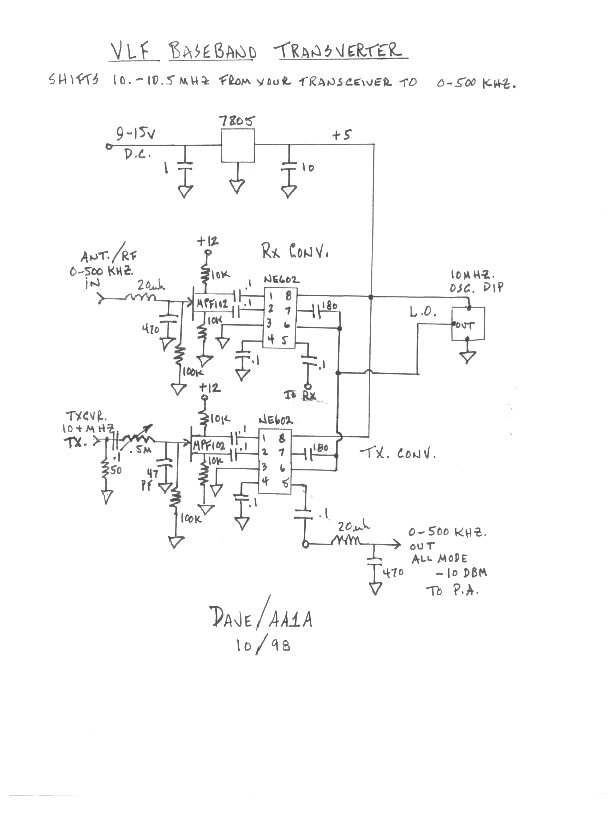
This tranverter covers the 0-500kHz range and can be used with any HF tranceiver with a suitable transverter output.
This single board transmitter fits on a 178 x 128mm PCB and includes a variable crystal oscillator, low pass filter, tx / rx switching relays, 'optically coupled' over-current protection and VSWR protection.
Keying the drive to a class-D mosfet PA can create key-clicks due to the non-linear characteristic of the PA. A nice clean keying shape can be achieved by keying the supply with appropriate rise and fall times.
The 'transverter' (transmit and receive converter) was designed to work with a Yaesu FT707 transceiver, operating at 10 MHz. All of my best DX QSOs were made using this set up. More recently, I have modified the transverter to interface with my IC756PRO.
The 400 W power amplifier (PA) uses many of the components from an old KW1000 HF linear amplifier (including the original pair of 572B valves). The amplifier was purchased for under Ł200 and has been modified from a switch-tuned grounded-grid configuration to an aperiodic (untuned), push-pull amplifier, rather like the QRO Class B Modulators of the 1960s.
This PDF document presents a modern approach to digitally synthesized analog amplitude modulation boasting very high power efficiency, and linearity which is only a function of quantization error.
This PDF document carries the Digital Amplitude Modulator concept to the general purpose Digital Linear Amplifier. There is no restriction on modulation format except that orthogonal carriers may not be used. The output is a distortion free power reproduction of the driving signal with or without carrier and with or without both sidebands since it is virtually impossible to stray away from a straight-line transfer function.
There are 3 circuits - the Phase Keying Signal Shaper shapes the phase modulating signal before it is applied to either the Linear BPSK modulator, or the Variable Phase modulator. The circuits are designed for 10bits/sec for use with "Wolf" or "Coherent", and use a logic level phase keying signal available from COM port, EPROM keyer etc. Either modulator also requires a 137kHz carrier from an external source. A well-smoothed 12V supply is also required.
This design uses high Voltage FETs straight from the mains with no bulky / heavy transformer.
Be aware that building this PA requires sufficient experience in handing high voltages / high power.
As is common on LF, I usually run QRO on 136 kHz (400 watts). But, in May 2001, I started wondering whether the 136 kHz band would be suitable for QRP operation (i.e. operating with a TX power output of just 5 W). It certainly seemed unlikely because of the poor antenna efficiency achievable at a wavelength of 2200 m, when using an antenna just a few tens of metres in length.
But I decided to build a QRP TX for LF, and give it a try! The 'Marathon-Five' LF TX to be described uses: a FET VFO; FET buffer; 2N2222 amplifier + BC212 keying transistor; 2SC2166 driver; and a pair of 2SC2166 transistors in parallel.
Within the first week week several stations, at distances up to 122km were worked.
(6 July 2001)My first transmission experiments on 136 kHz band where based on a little TX build around surplus components, particularly the output transformer was wound on a TV EAT transformer. In Italy is impossible to find Philips 3C85 cores. For 200W transmitter I decided a more professional approach: buy a surplus switching power supply core and design the output transformer according to ARRL Handbook suggestions.
The success was assured at the first try, so I publish my experience for all people interested in this band.
(22 August 2001)This project includes a very stable VXO (variation on the DJ1ZB/DF3LP design) and a 5W power amplifier using a single IC (TDA2030 or A2030). This transmitter can either be used for QRPP tests or to drive an additional high power amplifier (eg. G0MRF design).
A narrowband audio filter can significantly improve the readibility of weak CW signals. But the major problem the most narrow filters suffer of is ringing. PA0LQ developed a 30Hz filter with minimal ringing. Further the design includes a noiseblanker to reduce powerline induced QRM.
Another version of this filter, modified by GW4ALG can be found here
A direct digital synthesis VFO for 0 to 6MHz. For many applications on 136kHz (as slow CW, DFCW and PSK31) a very stable VFO signal is needed.
Noise is always a problem on LF. If the LF DXer lives in a densely populated area, chances are that one kind of noise is worse than all the others. That noise is from many of the electrical appliances that interrupt the power mains due to SCRs at each zero crossing of the 60 Hz signal. It turns out that the predominant frequency of this noise is 120 Hz. If you suspect that this kind of noise is causing your problems, look at the output of an amplified loop or whip antenna with a scope synced to the line frequency. You should see a periodic spike pattern with the spacing between the spikes equal to a 120 Hz repetition rate.
It has generally been my experience that the AC line noise that is encountered in most home LF receiving installations comes from two sources. The first and most severe is by conduction through the AC supply line and its safety ground. The second is by either inductive or electrostatic (or both) near-field coupling to nearby AC lines. Fortunately, it is fairly easy to reduce or eliminate both sources of noise.
Operation on LF using small antennas from an urban or sub-urban location is a challenge in itself. But just one local source of noise can make it impossible to hear any amateur signals on the band. It was local noise that prompted me to build my first noise canceller.
Pulse sidebands from the LORAN navigation system which spread into the 136kHz LF band and often masks weak stations. With this signal canceller the LORAN pulse sidebands can be completely nulled out leaving the DX stations in the clear and making a major improvement to my 136kHz receive capability not to mention the relief from not having to listen through the constant clatter of the LORAN.
A short description of an experimental DDS. This DDS-development should not be a competitor to the readily available DDS systems and ICs from ANALOG-DEVICES et. al.
The goal was to develop a cheap, amateur solution. After tests and experience with a DDS, made of discrete HC-MOS circuits which filled a complete lab-pcb. The idea was to replace the glue-logic by software.
This project includes both theory and practice of DSS design