My old 8-foot receiving loop
An 8-foot base-station loop
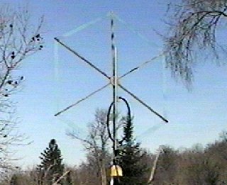
For several years, almost all of my longwave listening at home was done with the 8-foot loop pictured below. I included a brief description of this loop in an article in the March 1995 LOWDOWN. The article is available in the file libraries section of the Longwave Web page . Some of the description below is pasted from that article. The loop had 10 turns of #24 Teflon-insulated wire that I got at a surplus store. It also had grounded #14 inner and outer "turns" that were intended to provide some shielding. Of course, these "turns" were open at the center point, at the top of the loop. Otherwise they would effectively short out the signal. I don't whether or not this type of shield is really effective because I didn't try a similar loop without any shielding. The nulls were less than 15 dB down from the pattern maxima. This isn't bad for an unbalanced loop, but since then I've entirely re-built the loop in a balanced configuration as described later.
My old 8-foot receiving loop
Construction details for the old 8-foot loop are shown in the sketch below. Six unpainted pine 1 inch by 2 inch by 4 foot spokes attached to a plywood hub made up the support frame for the loop. The #24 insulated windings were about 1/4 inch apart and were set into saw slots in the edges of the 1 by 2's, so that the windings were all in the same plane. With the saw slots angled toward the center, the tension on the windings kept the wires in place over a period of several years. Holes drilled through the spokes would hold the wire in place even better, but the loop would be almost impossible to wind. The loop looked like the outer part of a giant spider web. I expected the loop to fall apart after the pine 1 by 2's had weathered for a couple of years, but it stayed up for over five years and was still hanging together. In fact, my new loop is wound on the same old weathered pine boards.
The picture below shows the present 8-foot loop, wound with sixteen turns of #26 insulated wire (I got a mile or more of the stuff from a surplus store in Minneapolis a few years ago). Although the loop is built on the same frame as the loop I had used for several years, I have gone from a spiderweb kind of winding with the wires held by saw slots in the 1x2 spokes to a flat winding using home-made plexiglass "combs" on the ends of the spokes. A close-up of one of the combs shows what it looks like -- basically a piece of plexiglass with saw slots every 4 mm (actually about 5/32 inch), held to the 1x2 spoke with a couple of screws. After a little over a year of wind, snow and ice, the windings aren't quite as straight as when the loop was built, but it still works the same. The hub construction is shown in the third photograph. Just a circle of plywood with the 1x2 spokes attached edge-on with wood screws.
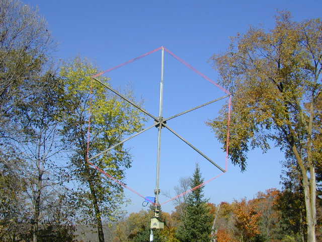
The 8-foot receiving loop, reincarnated in balanced configuration
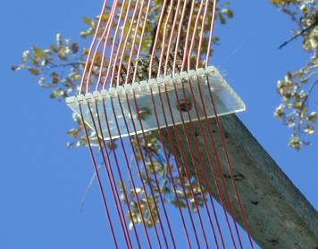
Details of plexiglass "comb" and windings
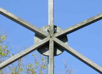
Hub construction
The receiving loop is about 60 feet from the house, and the remote-tuned balanced preamp is mounted on the support mast. The mast is turned by a standard TV rotator. I found that I had to put a PVC insulating section in the support pipe, below the rotator. Otherwise the ground currents flowing through the intermittent electrical path in the rotator create a lot of electrical noise while it is turning. The bottom of the loop is less than six feet above the ground -- just enough so it's easy to mow around it. Height above ground has very little effect on an LF receiving loop's performance.
The inductance of my old loop was less than 1000 uH, and it took three MVAM109 tuning diodes in parallel to tune it to the LowFER band. That was in a "single-ended" configuration. For best Q and least susceptibility to intermod, the tuning diodes should be connected as back-to-back pairs. With a pair of diodes acting as capacitors in series, the total capacitance is cut in half, so it takes four times as many diodes to get the same capacitance range in a back-to-back configuration as in a single-ended circuit. Out here in the boondocks I seemed to get by OK with the single-ended tuning diode arrangement, but it might be a disaster if there were strong broadcast stations near by. My new loop uses the balanced preamp circuit shown elsewhere on my web page. The loop inductance is high enough so that it will tune down into the LowFER band with four MVAM108 or MVAM109 diodes in a back-to-back circuit. Since my primary interest is in listening for LowFER signals, I have a fixed 470 pF capacitor across the loop terminals. This improves the overall Q slightly because the tuning diodes do not need to be operated at maximum capacity (near-zero bias voltage) to tune the loop down to the LowFER band. The shunt capacitor also allowed me to listen (although unsuccessfully) for the AMRAD beacon and other signals in the 137 kHz range. Actually the loop has enough sensitivity, and the preamp has high enough gain, so that if I tune it to the middle of the band it will pick up LowFER signals from 175 to 190 kHz with no retuning. Because the loop efficiency increases so rapidly with increasing frequency, I normally do not even find it necessary to retune in order to hear NDBs throughout the 190 to 530 kHz range.
Portable loops
For portable LF listening other than casual checks with the built-in whip on a Sony 2001, I sometimes use a Hustler 5/8-wave magnetic-mount 2 meter whip on the top of the car. Sensitivity is adequate with my high-gain preamp in the "low Z" position to hear LowFERs at 100 miles or more. A loop works much better, but in cold weather it's a lot more comfortable just to disconnect the antenna lead from the 2-meter rig and hook it up to the LF receiver. Sticking your hand out the car window to hold the loop isn't the kind of thing you want to do for very long during a Minnesota winter.
My favorite portable LF antenna is a 30-inch loop wound with about 23 turns of #26 plastic-insulated wire inside a circle of 3/4-inch black plastic utility pipe. A Hula Hoop would be about the same size. Bigger loops and larger wire will improve the signal, but the 30-inch loop is a very good compromise. Discount building supply stores sometimes have the pipe on sale at less than 10 bucks for a 100-foot coil, which will make a lot of loops. You can wind the loop by cutting off a piece of pipe and forming it into a circle (which is the shape it wants to be, anyway), and taping the open ends of the pipe (or Hula Hoop) to a stick to hold them about 6 or 8 inches apart. If the loop is going to be wound with wire that is too flexible to push through easily, a "leader" wire can be used. Push a piece of stiff wire, like #14 house wire, through the pipe until the wire goes all the way around and the wire ends overlap. Tape or solder the wire ends together, and tape the wire you will use for the windings to the heavy wire. Then you can just keep working the wire around the circle, 6 inches at a time, until you have the desired number of turns. Sounds difficult, but if the wire and pipe are slippery enough it goes surprisingly well. Actually easier than most coil winding operations. I've managed to get 16 turns of #14 insulated building wire into a 3-foot circle of 3/4 inch utility pipe before it started to bind up, and with smaller wire it's easy to get a lot more turns. Please note that more turns aren't always better. Too many turns (more than about 25 turns for a loop of this type used in the 150-500 kHz range) will lower the self-resonant frequency to the point where the loop can no longer be tuned properly. After you have the desired number of turns, you can pull out the stiff wire, and pull on the ends of the winding to bring the ends of the plastic pipe together. It may be necessary to stuff some excess wire inside the pipe if it won't pull tight by itself. Then I usually take an 8-inch length of plastic pipe that has been slit lengthwise and force it over the ends of the circle, finally wrapping the joint with tape to hold it together. Probably you could get by with just a generous application of duct tape. The nice thing about this kind of loop is that it doesn't have any sharp edges, and it can be squished into a shape that will fit into available space in the car. When using a portable LF or MF receiver with a built-in loopstick antenna, it is usually possible to improve the sensitivity dramatically just by placing the radio in or near a large loop and tuning the loop to resonance. However, a high-gain preamp is needed to hear really weak longwave signals with almost any reasonable-sized loop.
In the picture below, six homebrew portable loop antennas are shown for comparison. The largest is a 48 inch diameter series-tuned loop; next is a 36-inch loop and then the "favorite" 30-inch loop with a wooden mounting bracket for attachment to the car's roof rack (while the car is stationary). Inside the 30-inch loop is an 8-inch loading coil wound with #22 double cotton covered wire on a form made from two circles of 2-inch thick styrofoam glued together. That's the red and pink cylinder with the electrical tape around it. There is also a large bundle of ferrite rods sent to me by Bill Bowers, and a smaller bundle of four 3/8 inch diameter by 6 inch long ferrite rods. As far as reception capability, size pretty much tells the story. Best results are obtained with the 48 inch loop, followed by the 36 and 30 inch loops. The 8-inch coil, originally used as a temporary loading coil for a LowFER transmitting antenna, and the large bundle of ferrite rods are not quite as good as the 30-inch loop, but are both capable of hearing LowFER BK at a distance of almost 100 miles. I haven't done any experiments with different windings on the large ferrite antenna, which might improve its performance considerably. Using the small bundle of ferrite rods, I can hear strong NDBs but no LowFERs at this location.
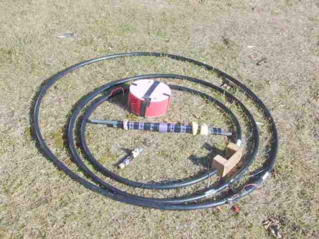
A collection of portable LF loops
Loop design considerations
It's fun to experiment with different loop configurations to see which ones work best with the materials you happen to have on hand. After gaining a little experience, the trial and error approach works fairly well. However, there are some fairly painless techniques for designing a loop that will work right the first time. One of the first questions to ask is "How big does the loop have to be?" Because loop efficiency is roughly proportional to the cube of its effective diameter, a slight increase in size will usually give a large improvement in performance. However, there is a point beyond which there won't be much signal-to-noise improvement as the loop size is increased. A good rule of thumb is that a well-constructed 6-foot or larger loop should be able to reach the "noise floor". That is, the atmospheric and man-made noise picked up by the loop will be stronger than the thermal noise in a good receiver or preamp. Of course the background noise level can vary greatly, depending on location. Out in the boondocks in central Minnesota, the noise level is sometimes (not often) very low. But in an urban setting and/or at a more southern latitude where the winter thunderstorms are much closer, the noise level can be many dB higher, and using a huge loop may not cause much improvement in signal to noise ratio.
Other factors in loop design are the wire size and the number of turns. Theoretically, the number of turns in the loop does not really determine the efficiency. For a given loop size, what really matters is the total amount of copper. One fat turn will do as well as a lot of skinny wires. In practice, though, there will be an optimum number of turns that depends on how you plan to use the loop. I prefer to use a FET input stage with a parallel-tuned, multiturn loop. Reg Edwards' RJELOOP3.EXE software (check the G4FGQ web site link on my home page) provides a good way to check out a loop design prior to building it. Although the software is for square loop configurations, a circular loop or other shape with roughly the same enclosed area as the square will have very similar characteristics. RJELOOP3 will provide a long list of parameters; just about everything you would ever want to know about an antenna. I usually ignore most of the data except for the lines that tell me what value of capacitance is required to tune the loop to the specified frequency, and the receiving sensitivity with respect to a quarter-wave vertical. For example, RJELOOP3 says that a 2-meter square loop with 19 turns of 1-mm diameter (#18 AWG) wire, with a turns spacing of about 0.25 inch (ratio of pitch to wire diameter = 6) will tune from 160 to 530 kHz with a 30 to 500 pF capacitor and has a "gain" of -57 dB at the bottom of the LowFER band. This should be a very good longwave receiving antenna.