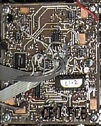
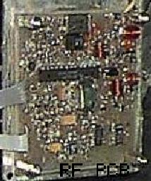
The sniffer is constructed on two circuit boards (RF and CPU). The RF board contains all the RF circuitry with gain control, phase locked loops and detection circuits. The CPU board holds the microprocessor, analog conversion, power supply, TX ALC, audio switching, audio VCO, audio amplifier and FM link circuits.
CPU Card and RF Card of original sniffer kit:
Rear of the CPU card (showing buttons and 3.5mm connector):
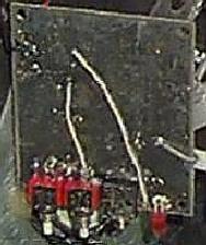
The components are all surface mounted (except the buttons and the 3.5mm socket) and surface mount components have been used where possible to keep the size down.
A box was chosen that was relatively cheap, rugged and could be easily made waterproof.
The kit is provided as a kit of parts. The box will need finishing and holes drilled for the buttons, sockets, led and speaker. A set of construction articles takes the constructor step by step through the construction process, and details how to test and align the sniffer once it has been built.
Equipment you will need to construct the kit are metal files, drill bits & drill, screwdrivers, soldering iron with a small tip, solder (thin) and a multimeter. A signal source & receiver such as a handheld is useful for alignment. An oscilliscope will assist with debugging. If you have access to a spectrum analyser and an adjustable RF oscillator alignment can be quicker and easier.
The construction articles, circuits, component overlays and mechanical drawings are provided to a kit purchaser preferrably by Email to reduce the mailing costs. Pictures/ Circuits are in Postscript format.
Support via Email will be available from bruce@martin.com.au and david.beard@spa.com.au.
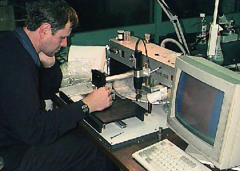
Here is Jack VK3WWW building his sniffer with the added luxury of being able to use a small pick and place machine: