Power line is used to transfer
electric energy from electric generator to
your daily electric equipments.Every
building has power line, including your house does.
If a building need electric energy, it
should get connected to electric
supplier (maintain by the state).
You can figure it out that all of buildings are connected through this
power
line.
So, I can say that we've already have a
"network" before internet was
launched.
The main function of power
line is ditributing electric energy.
Can we make a new function like sending
signal or data? The answer is yes,
you can.
We can inject a new signal to power line,
with your own need.
FCC rule said that a range of frequency
between 65kHz-75kHz at power line
can be used to send data or signal.Here is
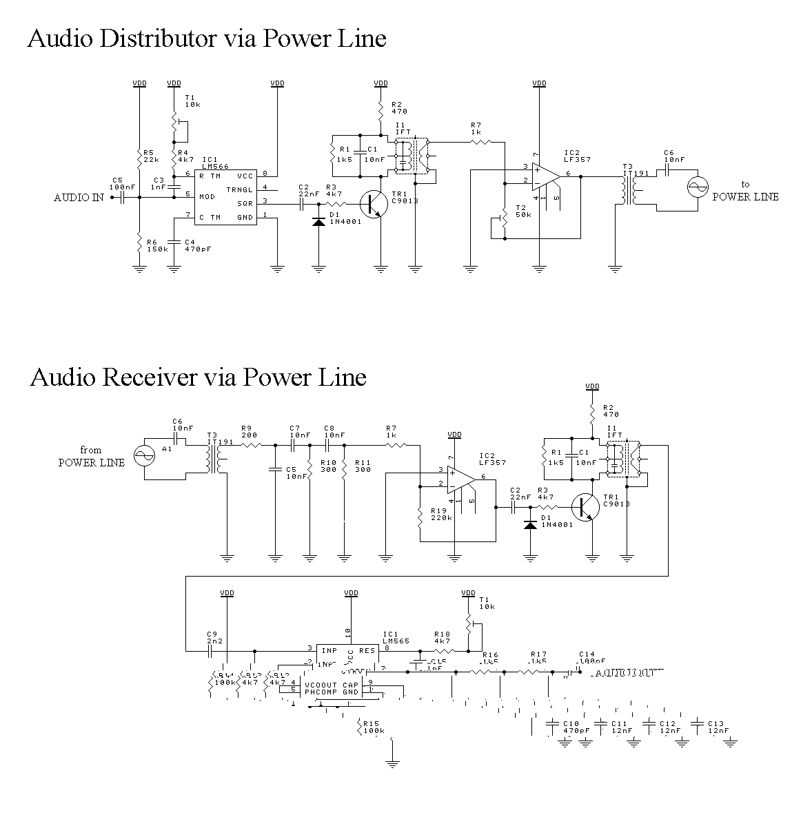
enclosed my circuit which send audio signal encoded in FM mode through
power line and a receiver to decode it from.
Electric power that run at
power line has a shape of sinusoide, in electrical ways it contain
amplitude and frequency.
First, injected signal may not annoying main
signal, so you must send as small as possible on. But remember, there
are always noises at the line. The point is, you must send a small
signal but large enough compared to the noises. The second, use range
permitted, that cause a modulation involved.
In this case I use frequency modulation
methode with 70kHz as the carrier
frequency.
Each component can be
constructed at two PCB. One as the transmitter and the other as
receiver. You can build more than one receiver, as example, you need
to hear music at living room, kitchen, bedroom, etc. Tune
potensiometer T1 at both transmitter and receiver to get the same
frequency (like tuning your radio). You might need osciloscope to get
the exact one. Then trim IF transformer to get best sinusoide carrier.
Use 455kHz IF tranformer with yellow painted ferrite core (it
frequency has
shifted about 70kHz by capasitor parallel
at).
Potensiometer T2 to set the
amount of carrier level injected at power line. Don't worry about have
or don;t have osciloscope. You can set it up by hearing the best sound
quality. Just put an audio source at the transmitter and an earphone
at the receiver. You might need an amplifier to get louder output.
Happy constructing and don't
forget to e-mail me. I'd like to hear from you.